Quadcopter
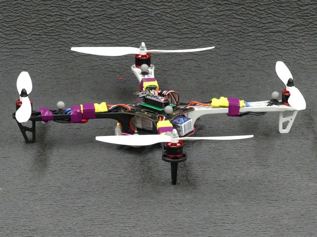
Autonomous devices rely on control schemes that ensure a smooth transition from one state to another. In this project, I’m looking to design a flight controller that demonstrates the properties of PID control. As an added challenge, I’ve used the cheapest components possible. The copter relies on an Arduino Nano for processing and an NRF24L01 for communication. The control originates in a 12 camera motion capture system and the PID gain is calculated in MatLab. The motivation here is for teaching control in UW’s “ME 439: Introduction to Robotics”, where students can implement their own controllers.
V2
Version 2 was the first time the craft looked elegant. The first frame I assembled in about 10 minutes with acrylic scraps was a balance nightmare. Unfortunately, this one hit the pavement without grace after a serial buffer overflow issue. Most of the craft was salvageable, but the bottom joint required heavy taping; I ultimately abandoned this for a consumer frame. Also, while experimenting with voltage compensation, I blew the Arduino. This experience is a perfect example of “learning the hard way.” Trying to find the fast rather than the right way to develop may turn out poorly.
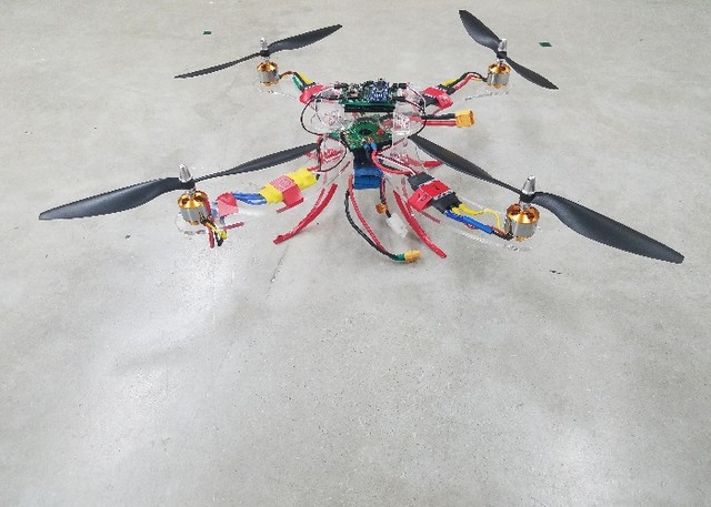
V3
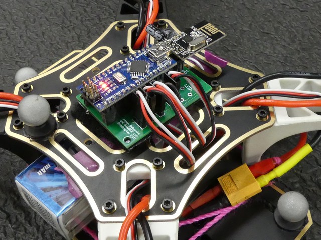
This version was finally the real deal; with a custom circuit board for the central components, headers, bullet connectors, and balance, it is in the air. The custom PCB, which replaces the protoboard, is an excellent addition to this craft. This allows me to switch Arduino boards if necessary. This was my trial by fire using Altium, but it turned out great! Ten boards expedited for $20 is all right. The 450mm frame included power distribution, which was a bonus. Hopefully, this one can take a beating.